

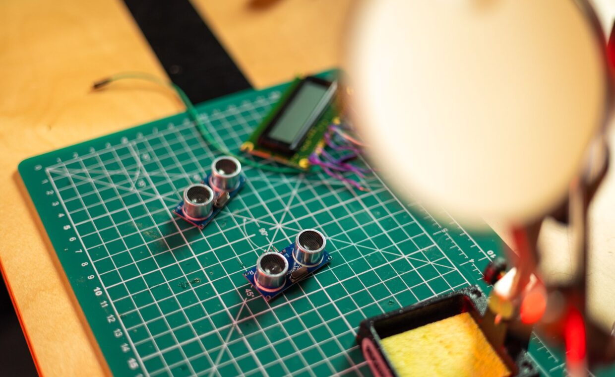
Every project that measures something real, heat, movement, light or distance, needs a sensor, and that is the point where tidy software meets messy wiring. Connecting one to a Raspberry Pi or an Arduino is not difficult, yet a few electrical rules decide whether you get clean numbers or a burnt-out pin. Grasping the split between digital and analog parts, respecting the board’s voltage limits, and recognising a handful of frequent mistakes will save hours of head-scratching. By the end you should be able to choose a sensor, wire it sensibly, and read its value in a few lines of code.
Digital and analog sensors
Sensors report in one of two ways, and the difference shapes how you wire and read them. A digital sensor hands the board a clean signal it can read directly, either a simple high or low for something like a motion detector, or a stream of numbers over a bus such as I2C or SPI for a temperature and humidity chip. The board understands these without extra parts.
An analog sensor instead outputs a voltage that varies smoothly with whatever it measures, a light-dependent resistor being the classic case. That voltage means nothing to a plain digital input until it is turned into a number. An Arduino has analog-to-digital converters built in, so it reads such sensors directly. A Raspberry Pi does not include one, which surprises many newcomers and shapes the wiring below, though it rarely limits the variety of projects a Pi can drive.
Voltage levels and staying safe
The single rule that protects your board is to know its logic voltage and never exceed it. A Raspberry Pi’s GPIO pins run at 3.3 volts and are not tolerant of 5 volts, so feeding a 5 volt signal into one can damage the pin or the whole chip. Many Arduino boards run their logic at 5 volts, though several newer models use 3.3.
This matters because plenty of sensors are sold as 5 volt parts. Powering the sensor from 5 volts is often fine, but its data line may then swing up to 5 volts, which a Pi input cannot accept. Matching or shifting those levels is essential, and the guide on protecting GPIO pins with level shifting covers the small circuits that do it safely.
Pull-up and pull-down resistors
A floating input is a common source of flickering, random readings. When a pin is not actively driven high or low, it picks up electrical noise and reports nonsense. A pull-up resistor gently ties the pin to the supply voltage so it reads high until something pulls it low, and a pull-down does the reverse, holding it low until driven high.
Many buttons and simple sensors rely on this. Helpfully, both the Raspberry Pi and the Arduino have internal pull-up resistors you can switch on in software, so you often need no extra components. I2C sensors need pull-ups on their two data lines, though small breakout boards usually include them already. Forgetting them is a frequent reason an I2C device never appears at all.
Terms worth knowing
A few words come up constantly once you start wiring sensors. The table below gives quick, plain definitions to keep beside you.
| Term | What it means |
|---|---|
| GPIO | General-purpose pins that read or drive digital signals |
| Logic level | The voltage counted as a digital high, usually 3.3V or 5V |
| ADC | Analog-to-digital converter, turning a voltage into a number |
| I2C | A two-wire bus letting several digital sensors share pins |
| Pull-up | A resistor holding an idle pin at a known level |
Reading values in code
With the wiring right, reading a sensor is short work. For a digital pin, you set it as an input and check whether it is high or low, and a library turns that into a True or False your program acts on. For an I2C sensor, a library handles the bus traffic, and you call a read function that returns temperature or pressure in real units.
Analog sensors on a Pi need an external ADC chip, often an MCP3008, wired over SPI. A library reads a channel and gives back a number from 0 to 1023, which you scale into the quantity you care about. Sampling faster than the project needs wastes processor cycles and generates heat, the same trade-off weighed in the notes on overclocking a single-board computer.
Common wiring mistakes
Most sensor problems trace back to a short list of errors. Swapping power and ground, or mixing up the data and clock lines on an I2C part, stops it responding. Forgetting a common ground between the sensor and the board, especially when they run from separate supplies, gives readings that drift or vanish entirely.
Other frequent trips include feeding 5 volt logic into a 3.3 volt pin, leaving an input floating with no pull resistor, and confusing a sensor’s power rating with its signal voltage. Loose breadboard connections cause intermittent faults that look exactly like software bugs. When a sensor shares a build with a camera or another add-on, plan the shared pins early, something the guide on adding a camera to a Pi build also flags.
Getting reliable readings
Clean sensor data comes from getting the basics right rather than from clever code. Confirm the logic voltages match or are shifted, give every device a shared ground, add pull-ups where a bus or button needs them, and keep wiring short and firm. Most of the frustration beginners feel comes from one of these being wrong, not from a faulty sensor. A multimeter and a little patience diagnose more sensor faults than any amount of rewritten code.
Build up slowly. Wire one sensor, read it, prove the number makes sense, then add the next. That habit turns a tangle of mystery faults into a series of small, solvable steps, and it makes the eventual project far easier to trust when it is reporting on something you care about.
Frequently asked questions
How do I connect a sensor to a Raspberry Pi?
Wire the sensor’s power and ground to the matching Pi pins, then connect its signal line to a GPIO pin, checking the voltage is 3.3 volt safe first. Digital and I2C sensors connect directly, while analog sensors need an external ADC chip. Enable I2C or SPI in the Pi’s settings if the sensor uses one, then read it with a suitable library.
Can a Pi read analog sensors?
Not on its own, because the Raspberry Pi has no built-in analog-to-digital converter. To read an analog sensor you add an external ADC chip such as an MCP3008, wired over the SPI bus, which converts the varying voltage into a number the Pi can use. An Arduino, by contrast, has analog inputs built in and reads such sensors without extra hardware.
Why is my sensor reading wrong?
Common causes are a missing common ground, a floating input with no pull-up resistor, or a voltage mismatch between the sensor and the board. Loose connections and swapped data lines also produce odd numbers. Check the wiring against the sensor’s datasheet, confirm the logic voltages match, and test the sensor alone before blaming your code, which is usually innocent.