

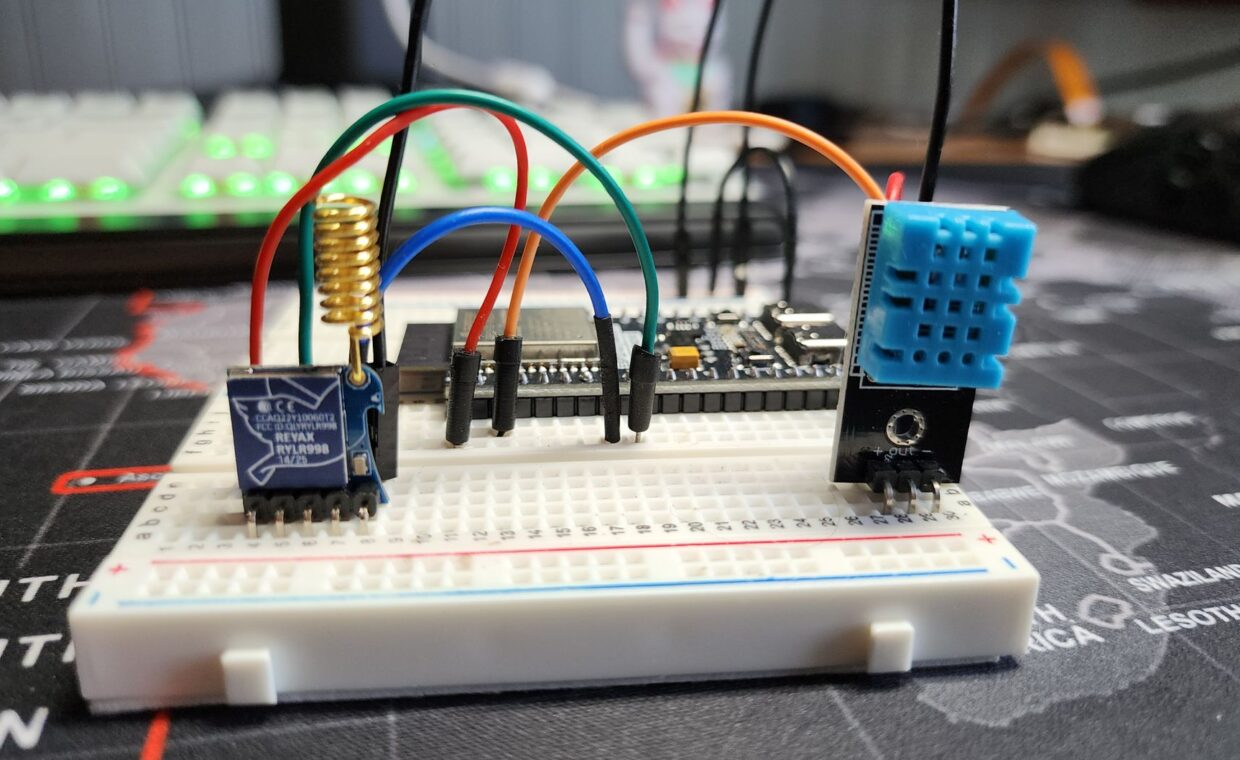
Connecting a 5V sensor to a 3.3V input pin is one of the quickest ways to damage a small board. The board’s processor expects signals that swing between zero and 3.3 volts, and a part designed for 5 volt logic can push more than the pin is built to accept. Level shifting is the practice of translating between those voltages safely, and a few habits around it protect the pins from spikes, wiring slips, and too much current. This guide explains why the mismatch happens and how to wire around it without losing hardware.
Why 3.3V and 5V parts collide
Different chip families settled on different logic voltages, and the two most common in hobby electronics are 3.3V and 5V. A logic high on a 5V part can sit near 5 volts, while a 3.3V input treats anything above roughly its own rail as out of range. Feed that higher voltage straight in and current flows through the pin’s internal protection in a way it was never meant to carry.
The header itself hides this, because a single connector often mixes power and signal pins. A clear map of what each pin on the header does helps you tell a 5V supply pin from a 3.3V logic pin before anything is connected, which is where most mistakes begin.
The direction of the mismatch decides how much trouble it causes. A 3.3V output driving a 5V input is often fine, because many 5V parts count anything above about 2 volts as a logic high, so the lower signal still reads correctly. The dangerous direction is the reverse, a 5V output feeding a 3.3V input, where the pin sees a voltage above its own rail. Knowing which way a signal travels tells you whether a shifter is needed at all, or only on some of the lines.
What a level shifter actually does
A level shifter translates a signal from one logic voltage to another so both sides see levels they understand. A simple version uses a single transistor and two resistors per line, common on the small bidirectional boards sold for exactly this purpose. Others use a dedicated buffer chip that converts several lines at once and drives them cleanly.
Direction matters. Some shifters work either way on a line, which suits shared buses like I2C, while others move signals one way only, which fits a sensor feeding data into the board. The range of add-ons that need this translation, from displays to motor drivers, runs across the many builds explored in the guide to what these boards are good for, so a shifter is a part worth keeping in the drawer.
For a signal that only needs stepping down, from 5V to 3.3V in one direction, a plain resistor divider can serve on slow lines. Two resistors in roughly a 1.8 to 3.3 ratio drop the voltage to a safe level, though the divider blurs fast signals and cannot lift a 3.3V output up to 5V. A dedicated shifter avoids both limits and drives either direction where a shared bus needs it, which is why prebuilt modules are popular for I2C.
How much current a pin can pass
Voltage is only half the picture. Each GPIO pin can source or sink a limited current, often around 16 milliamps as a safe figure on common boards, with a lower ceiling across all pins combined. Drive an LED without a resistor, or try to power a small motor straight from a pin, and you exceed that limit quickly.
Anything hungrier needs its own supply, switched by a transistor or a driver rather than pulled through the pin. The board’s own intake sets the ceiling for everything downstream, which is why understanding how the board draws power over USB matters before you hang several parts off the header. Add a resistor to every LED, and give motors, relays, and long LED strips a separate feed.
Guarding inputs from spikes and mistakes
Inputs deserve protection because they face the outside world. A series resistor of a few hundred ohms between an external signal and the pin limits current if the voltage ever climbs too high, turning a dead pin into a survivable event. For lines that might see brief spikes, a small clamping diode to the rail bleeds off the excess.
Floating inputs cause a different problem, reading randomly high and low until a pull-up or pull-down resistor ties them to a known level. Losing a pin, or a whole board, hurts far less when your data already sits elsewhere, the habit the guide on keeping a home server recoverable makes routine. Wire defensively and a wrong connection costs a resistor, not the board.
A safe bring-up sequence
Testing before applying power catches the errors that cost hardware. Work through the wiring methodically rather than plugging in and hoping.
- Check every connection against the pinout with the board unpowered, confirming grounds are common and no supply pin touches a signal line.
- Measure the peripheral’s output voltage on its own supply, verifying it truly sits at 5V or 3.3V as expected.
- Confirm the level shifter is oriented correctly, with its high side on the 5V supply and its low side on the board’s 3.3V rail.
- Power the peripheral first, without the board connected, and check the shifted voltage on a meter.
- Only then connect the board, bring it up, and test one signal line before trusting the whole circuit.
Bringing it together
Protecting GPIO is less about a single component and more about a set of small precautions applied every time. Match voltages with a shifter, respect the current a pin can pass, add series resistors and pull resistors where they belong, and never skip the unpowered check. Each step is cheap on its own, and together they turn a fragile circuit into one that tolerates the occasional slip.
The reward is confidence to experiment. When a mistake costs a resistor rather than a board, you try more connections, learn faster, and build circuits that keep working after the excitement of the first power-up fades. Treat the pins as the delicate, limited interface they are, and they will outlast many rounds of tinkering.
Frequently asked questions
Can I connect 5V to a Pi GPIO?
Not to a signal pin. The GPIO logic pins are 3.3V and can be damaged by 5 volts applied directly. The header does carry 5V supply pins for powering parts, but those are separate from the input and output lines. To read a 5V signal, pass it through a level shifter or a resistor divider so the pin only ever sees 3.3 volts.
What is a level shifter?
A level shifter is a small circuit that translates logic signals between two voltages, most often 3.3V and 5V, so parts on either side see levels they can read safely. It can be a single transistor with two resistors per line or a dedicated buffer chip handling several lines. Some are bidirectional for shared buses, others move a signal one way only.
How do I protect GPIO pins?
Add a series resistor of a few hundred ohms to external inputs, use pull-up or pull-down resistors so floating pins read a known state, and keep current within the per-pin limit by driving hungry loads through a transistor. Match voltages with a level shifter, and always check wiring with the board unpowered before the first power-up. These habits prevent most damage.