

The forty metal pins along the edge of a Raspberry Pi look inviting, and plenty of first projects end with a dead board because a wire went to the wrong place or carried the wrong voltage. Grasping a handful of electrical basics prevents almost every one of those early accidents. This guide covers the logic voltage the pins expect, why five volts is dangerous, how much current a single pin and the whole header can supply, what pull-up and pull-down resistors do, the split between input and output modes, and how to read a pinout without miscounting a row.
Logic voltage and the five-volt trap
A Raspberry Pi’s general-purpose pins run at 3.3 volts. A high signal is 3.3 volts, a low signal is zero, and the chip reads anything in between as one or the other using a threshold near the middle. The header also carries 5-volt pins, but those are power outputs taken from the board’s input supply, not signal lines, and that distinction catches many newcomers off guard.
Feeding 5 volts into a 3.3-volt input is the classic first-week mistake. The pin has no headroom for it, the voltage exceeds what the processor is built to accept, and the damage is often permanent and invisible. Many sensors and older Arduino boards speak at 5 volts, so wiring them straight to a Pi invites trouble, a pairing the primer on joining an Arduino to a Pi handles with care. A level shifter or a simple resistor divider brings the signal down to a safe level before it reaches the pin.
Current limits per pin and overall
Voltage is only half the picture; current matters just as much. Each pin can safely source or sink in the region of 16 milliamps, and pushing far past that stresses the output driver until it fails. There is also a combined budget across the whole header, historically around 50 milliamps in total on older models, so lighting a dozen LEDs straight from the pins is asking for trouble even when each one seems modest on its own.
The practical rule is that pins signal, they do not power motors, relay coils, or long LED strips. An LED still needs a series resistor, commonly a few hundred ohms, to hold its current inside the limit. Anything hungrier belongs behind a transistor, a MOSFET, or a dedicated driver chip that takes its energy from a separate supply and uses the pin only as a switch. Driving several outputs while the processor works also raises the board’s temperature, the thermal side the explainer on keeping a board cool under load deals with.
Pull-up and pull-down resistors
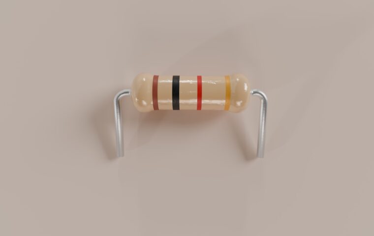
An input pin connected to nothing floats, picking up stray voltage and reading high or low at random. A pull-up resistor ties the line gently to 3.3 volts so it reads high while idle; a pull-down resistor ties it to ground so it reads low while idle. A button then connects the pin to the opposite rail when pressed, giving a clean, predictable change the software can trust.
The Raspberry Pi has internal pull-ups and pull-downs of roughly 50 kilohms that you switch on in software, which covers most simple buttons without extra parts. External resistors around 10 kilohms do the same job when you want a defined value or need one on a shared bus. A settled resting state matters most for anything meant to run untouched for weeks, the concern our look at projects left running on their own addresses.
Input and output modes
Every pin is configured before use as either an input, which reads the voltage placed on it, or an output, which drives a voltage itself. Setting a pin to output and then wiring it to another output or to a fixed voltage creates a contest that one side loses, usually the pin. Deciding the direction in software first, then wiring to match, avoids that clash entirely.
Some pins carry alternate roles beyond plain switching, such as the I2C, SPI, and UART buses, or hardware PWM for smooth dimming and servo control. Those functions have to be turned on and assigned to the right pins, which is why two projects can use the same physical pin for entirely different purposes. These modes are what let the header switch lights, read sensors, and talk to add-on boards, the span of jobs our rundown on common board projects surveys.
Reading a pinout without miscounting
Three numbering schemes cause endless confusion. Physical numbering counts the pins one to forty by position. The BCM scheme uses the processor’s own labels, which do not follow the physical order, and most libraries expect these. An older scheme called WiringPi added a third set and is now discouraged. Pin one is marked on the board, often with a square pad or a printed number, and orientation decides everything, since counting from the wrong end sends a wire two rows off.
The header alternates power and signal in a fixed pattern: 3.3 volts and 5 volts at set positions, several grounds spread along its length, and the rest general-purpose. Before wiring, confirm which scheme your code uses and count carefully from the marked pin. The short glossary below gathers the terms that trip people up most.
| Term | What it means | Why it matters |
|---|---|---|
| Logic level | 3.3 V high, 0 V low on a Pi | A 5 V input can kill the pin |
| Source and sink | Current flowing out of or into a pin | Stay near 16 mA per pin |
| Pull-up resistor | Ties an idle line to 3.3 V | Stops an input floating |
| BCM number | The processor’s own pin label | Most libraries expect it |
| Level shifter | Translates between 5 V and 3.3 V | Lets 5 V parts connect safely |
Keeping a board alive
Almost every ruined pin traces back to one of two errors: the wrong voltage or too much current. Respect the 3.3-volt logic level, shift anything running at 5 volts before it reaches an input, keep each pin near its milliamp ceiling, and route real loads through a transistor or driver. Those few habits protect the board through the messy trial and error that learning always involves.
The rest is bookkeeping. Decide each pin’s direction, give inputs a defined resting state with a pull resistor, and count from the marked pin using the numbering your code expects. None of it is difficult once the reasons are clear, and a board that survives its first week of experiments tends to survive for years of tinkering afterward.
Questions people ask most
Can I connect 5V to a Raspberry Pi GPIO?
No, not to a general-purpose input. The pins are rated for 3.3 volts, and 5 volts on an input can permanently damage the processor. The 5-volt pins on the header are power outputs, not signal lines. To read a 5-volt sensor or an Arduino output, place a level shifter or a resistor divider in between so the signal arrives at a safe 3.3 volts.
How much current can a GPIO pin supply?
A single pin can safely source or sink around 16 milliamps, and the whole header shares a limited budget, historically near 50 milliamps on older boards. That is enough for an LED with a series resistor or a logic-level input, but not for motors, relays, or long light strips. Anything larger should draw from a separate supply and be switched through a transistor or driver.
What is a pull-up resistor for?
It gives an input a definite voltage when nothing else is driving the line. Without it, a floating input reads high or low at random and triggers false events. A pull-up holds the pin at 3.3 volts until a button or sensor pulls it to ground. The Pi has internal pull-ups you can switch on in software, so many buttons need no extra components at all.