

Wiring a single LED to a battery or a microcontroller pin looks trivial until the LED flares bright for a second and dies, or never lights at all. The missing piece is almost always a resistor of the right size, and picking that size takes one line of school physics rather than guesswork. This worked example runs the whole calculation for a common setup, from reading the LED’s own voltage figure to choosing a resistor you can actually buy and confirming it will not overheat. By the end the arithmetic should feel routine enough to repeat for any LED and supply you meet.
The one equation behind it
Ohm’s law ties together three quantities in a circuit: voltage, the push that drives current; current, the flow of charge measured in amps; and resistance, the opposition to that flow measured in ohms. The relationship is simply voltage equals current times resistance, or V equals I times R. Rearranged, resistance equals voltage divided by current. That single rearrangement is the whole tool for sizing an LED resistor, because you know the voltage you need to absorb and the current you want, and you are solving for the resistor that produces exactly that flow.
The two numbers the LED gives you
An LED is not a plain resistor; it drops a roughly fixed voltage once it conducts, called its forward voltage. A standard red LED drops about 1.8 to 2.0 volts, while blue and white types drop nearer 3.0 to 3.4 volts. The datasheet lists the exact figure, but these ranges are close enough for ordinary indicator use. The second number is the forward current you want to run, the flow that sets brightness. Many small LEDs are rated up to 20 milliamps, yet 5 to 10 milliamps is plenty for a visible indicator and runs cooler.
When the LED is driven from a microcontroller rather than a battery, the pin itself has limits, so the current you choose has to respect what the chip can safely supply, a constraint our rundown on how microcontroller pins work lays out. Pushing a pin past its rated current can damage it even when the LED itself survives.
Working a real example
Take a typical case: a red LED with a 2.0 volt forward drop, a 5 volt supply, and a target current of 10 milliamps, which is 0.01 amps. The resistor has to absorb whatever voltage the LED does not, so first find that leftover voltage. The supply is 5 volts and the LED keeps 2.0, leaving 3.0 volts across the resistor.
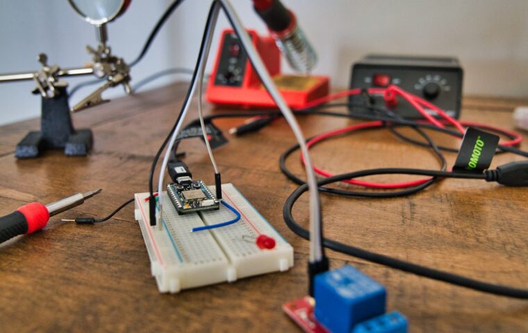
Now apply the rearranged law. Resistance equals the voltage across the resistor divided by the current through it, so R equals 3.0 divided by 0.01, which is 300 ohms. That is the ideal value: put 300 ohms in series with this LED on a 5 volt supply and about 10 milliamps flows, lighting it at a sensible brightness without stress. The same resistor sits happily in a breadboard build like the one described in the walkthrough on choosing a board for a first project.
Two details often trip up beginners. The resistor can go on either side of the LED, before it or after it, because in a series circuit the same current flows through every part, so the order does not change the maths. And if the subtraction ever gives a negative or near-zero figure, the supply voltage is below the LED’s forward voltage, meaning the LED will not light properly from that source and you need a higher supply.
Common combinations at a glance
The same three-step method gives these resistor values for frequent supply and LED pairings, all at a 10 milliamp target current.
| Supply | LED forward voltage | Voltage across resistor | Resistor (ideal) |
|---|---|---|---|
| 5 V | 2.0 V (red) | 3.0 V | 300 ohms |
| 5 V | 3.2 V (blue) | 1.8 V | 180 ohms |
| 3.3 V | 2.0 V (red) | 1.3 V | 130 ohms |
| 12 V | 2.0 V (red) | 10.0 V | 1,000 ohms |
Rounding to a real part and checking heat
Resistors are sold in fixed value steps, so 300 ohms may not be on the shelf even though it is a common value. If the exact number is missing, round up to the next available value rather than down. A slightly larger resistor lets slightly less current through, dimming the LED a touch but keeping it safe, whereas rounding down raises current and risk. Choosing 330 ohms instead of 300 drops the current to about 9 milliamps, a change nobody will notice by eye.
The last check is power, because a resistor turns the voltage it absorbs into heat. Power equals voltage times current, so here it is 3.0 volts times 0.01 amps, which is 0.03 watts. A standard quarter-watt resistor, rated 0.25 watts, handles that with enormous margin. Only high-current or high-voltage circuits need larger resistors, yet the check takes seconds and prevents a scorched part. Protecting a driving pin follows the same spirit of care, the subject the guide on keeping a control pin safe examines.
What this means in practice
Sizing an LED resistor comes down to three moves: find the voltage the resistor must drop by subtracting the LED’s forward voltage from the supply, divide that by the current you want in amps to get the resistance, then round up to a real value and confirm the power rating. The same steps work whether the supply is a 3.3 volt pin, a 5 volt board or a 12 volt strip, and only the numbers change.
Once the method is familiar it takes under a minute per LED, and it turns a component that seems fussy into a predictable one. That confidence carries into bigger builds, where several LEDs, sensors and modules share a supply, and it sits well alongside the simple wiring exercises in the roundup of beginner board projects to try. Learn it once on a single red LED and the arithmetic never really changes.
Answers to common questions
Why does an LED need a resistor?
An LED has very little internal resistance once it conducts, so connected straight to a supply it draws far more current than it can survive and burns out almost instantly. The resistor sits in series and limits that current to a safe level by absorbing the surplus voltage. Without it, nothing controls the flow, and the LED either flares briefly and fails or stresses the source driving it.
How do I calculate the resistor value for an LED?
Subtract the LED’s forward voltage from the supply voltage to find how much the resistor must drop, then divide that figure by your target current in amps. For a 5 volt supply, a 2 volt red LED and 10 milliamps, that is 3.0 divided by 0.01, giving 300 ohms. Round up to the nearest stocked value and check the power rating before wiring it in.
What happens if the resistor is too small or too large?
Too small a resistor lets too much current through, which overdrives the LED, shortens its life and can damage the supply or a driving pin. Too large a resistor restricts current so the LED glows dimly or barely lights at all. Aim for the calculated value, rounding up slightly for safety; a small increase costs a little brightness, while going too low risks the component.